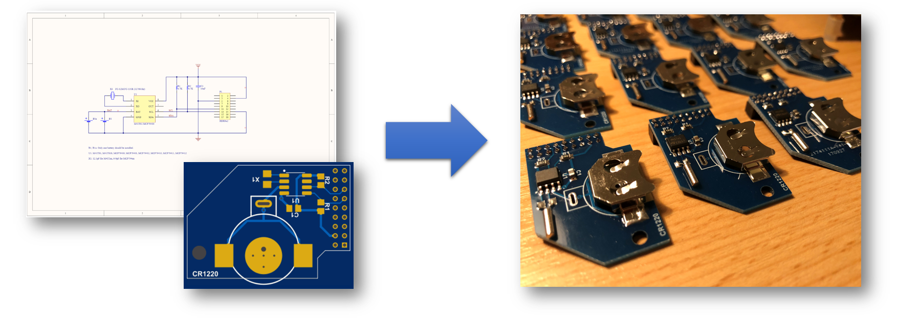
RTC board Assembly
NOTE
This page is for reference only. It may not be up to date. It may not include the BOM for latest PCB version. You need to check the schematic and required components yourself!
The following section will walk you through the steps of creating your own Mister RTC Board. It describes where to order all necessary parts like PCB and components. It will also give you an overview on the equipment you need and show you how to assemble the board.
1. Order PCB
Approved PCB Manufactors
PCB Layout (Gerber Files)
Check the MiSTer hardware repository for the most recent PCB files: MiSTer_Hardware
2. Order Components
This is a general overview of the components, including reference parts that were successfully used to assemble a MiSTer RTC Board version 1.2.
General Components:
The components in this table are the general components. You will have to choose additionally a RTC chip and crystal combination from the next table
| Name | Component | Package | Value | Reference Parts |
|---|---|---|---|---|
| C1 | Capacitor (Ceramic) | 0805 | 10uF | KEMET C0805C106K8PACTU |
| R1, R2 | Resistor 1% ⅛W | 0805 | 4.7K | Yageo RC0805FR-074K7L |
| B1 | Coin Cell Holder for CR1220 | 12mm | - | MPD BK-885 |
| P1 | GPIO Connector | 2mm | 18 Pin | Amphenol 63453-118LF |
RTC / Crystal Table
The RTC Chip (U1) / Crystal (X1) combination in this table are approved by users that successfully build a RTC Board version 1.2
| Name | Component | Package | Value | Reference Parts |
|---|---|---|---|---|
| U1 | I2C RTC Chip: M41T81 |
8-SOIC | - | ST M41T81M6F |
| X1 | Crystal: 32.768kHz ±20ppm, 12.5pF, 50 kOhms |
Cylindrical Can | - | Citizen CMR200T32768DZFT |