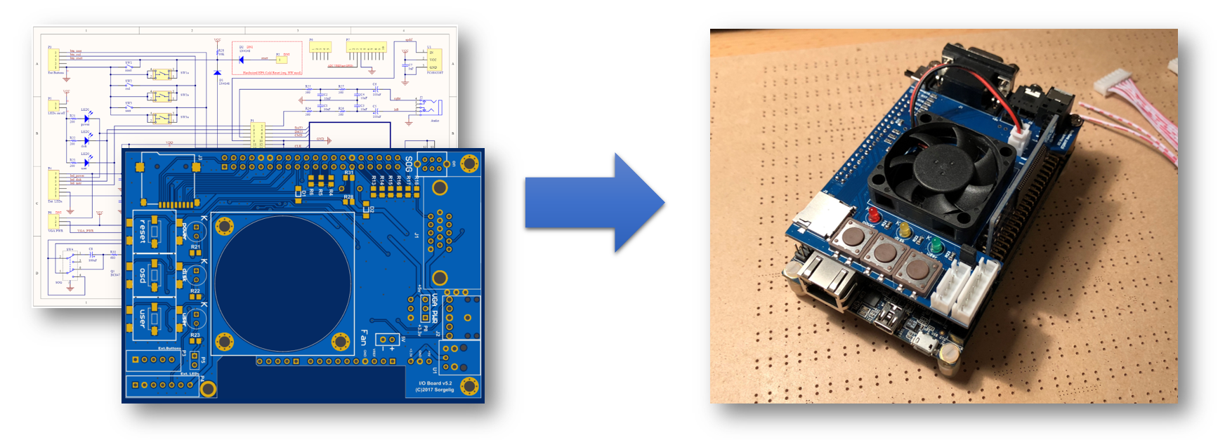
IO Board Assembly
NOTES
This page is for reference only. It may not be up to date. It may not include the BOM for latest PCB version. You need to check the schematic and required components yourself!
The following section will walk you through the steps of creating your own Mister IO Board. It describes where to order all necessary parts like PCB and components. It will also give you an overview on the equipment you need and show you how to assemble the board.
Important Note:
I/O board has an option to provide either +5V or +3.3V through VGA PIN9. It’s supposed to be used in some handmade active VGA adapters/converters. Some cables and displays have PIN9 grounded which will make short circuit if P8(VGA PWR) has jumper! It’s advised not to solder P8 at all, so PIN9 won’t have a power and it will be safe to connect any cable/display. Use P8 only when you are absolutely sure you need the power on PIN9.
1. Order PCB
Approved PCB Manufactors
PCB Layout (Gerber Files) and Schematics.
Check the MiSTer hardware repository for the most recent files here : MiSTer_Hardware.
The Gerber Files and Schematics are in the releases folder.
2. Order Components
This is a general overview of the components, including reference parts that were successfully used to assemble a MiSTer IO Board version 5.5.
Please refer to the PDF for more information.
| Name | Component | Package | Value | Reference Parts |
|---|---|---|---|---|
| C1, C2, C3, C4 | Capacitor (Ceramic) | 0805 | 10nF | KEMET C0805C103K5RACTU |
| C5, C6, C8 | Capacitor (Tantalum) | 2312 | 100uF | VISHAY 293D107X96R3C2TE3 |
| C7, C9, C10, C11, C12 | Capacitor (Ceramic) | 0805 | 10uF | KEMET C0805C106K8PACTU |
| R1, R7, R13 | Resistor 1% ⅛W | 0805 | 510 | YAGEO RC0805FR-07510RL |
| R2, R8, R14 | Resistor 1% ⅛W | 0805 | 1.1K | YAGEO RC0805FR-071K1L |
| R3, R9, R15 | Resistor 1% ⅛W | 0805 | 2.2K | YAGEO RC0805FR-072K2L |
| R4, R10, R16 | Resistor 1% ⅛W | 0805 | 4.3K | YAGEO RC0805FR-074K3L |
| R5, R11, R17 | Resistor 1% ⅛W | 0805 | 9.1K | YAGEO RC0805FR-079K1L |
| R6, R12, R18 | Resistor 1% ⅛W | 0805 | 18K | YAGEO RC0805FR-0718KL |
| R19, R20, R33-38 | Resistor 5% ⅛W | 0805 | 100 | YAGEO RC0805FR-07100RL |
| R21, R22, R23, R32 | Resistor 5% ⅛W | 0805 | 200 | YAGEO RC0805FR-07200RL |
| R24, R25, R26, R27 | Resistor 5% ⅛W | 0805 | 560 | YAGEO RC0805FR-07560RL |
| R28, R31 | Resistor 5% ⅛W | 0805 | 10K | YAGEO RC0805FR-0710KL |
| R29 | Resistor 5% ⅛W | 0805 | 1K | YAGEO RC0805FR-071KL |
| R30 | Resistor 5% ⅛W | 0805 | 680 | YAGEO RC0805FR-07680RL |
| D1 (D2 DNI) | General Purpose Diode | SOD80 | BAV100 | VISHAY BAV100-GS08 |
| LED1 | LED Red | 5mm | - | Hubei KENTO Elec 5AR2PD08 |
| LED2 | LED Yellow | 5mm | - | Hubei KENTO Elec C54170 |
| LED3 | LED Green | 5mm | - | Hubei KENTO Elec C54166 |
| LED4 | LED Red (small) | 3mm | - | Hubei KENTO Elec 3AR4PD08 |
| SW1, SW2, SW3 | Switch Tactile | - | - | E-Switch TL3300DF160Q |
| SW4 | Slide Switch, DPDT, On/On, Non-Shorting (BBM) | 2.54mm | - | C&K OS202011MA0QN1 |
| P1 (GPIO) | Female Header, Double Row, Isolation Height: 11.05mm | 2,54mm | 2x20P | No Name (AliExpress) OR BOOMELE (LCSC) |
| I2S (4 pins), VGA Power Select (3 pins) | Male Pin Header, Single Row | 2.54mm | - | SULLINS PRPC040SAAN-RC |
| P3 | Connector for External Buttons | XH2.54 | 5P | No Name (AliExpress) OR BOOMELE (LCSC) |
| P4 | Connector for External LEDs | XH2.54 | 7P | No Name (AliExpress) OR BOOMELE (LCSC) |
| P# (FAN) | Connector for Fan | XH2.54 | 2P | No Name (AliExpress) OR Ckmtw (LCSC) |
| P2, P5, P6 (DNI) | - | - | - | - |
| P7 (pins 1,2,4-8) P9 (1 pin) | Long Male Header | 2.54mm | 40 Pin (cut) | C51353 (Boom Preceision ELEC) |
| Q1 | Transistor NPN | SOT23 | BC847 | ON BC847BLT1G |
| J1 | VGA Connector, 15 Pos, 3 Row, Female Connector, Right Angle | D-Sub | - | Omron XM4L-1542-132 |
| J2 | Phone Jack 3.5mm, Right Angle | - | - | CUI SJ1-3523N |
| J3 | Micro SD-Card Holder | - | - | No Name (AliExpress) OR SOFNG (LCSC) |
| J4 | USB 3.0, Female, Right Angle | Type A | 9 pins | Jing C69073 |
| FAN | Fan | 40x40x10 | 5V | Sunon MF40100V2-1000U-A99 (Very Noisy) or Noctua NF-A4x10 5V (quiet, costly) |
| JMPR | Jumper for Pin-Header | 2.54mm | 2 Pin | Sullins SPC02SYAN |
| HEATSINK | Heatsink | 21x21x11.5 | - | Wakefield-Vette 624-45ABT3 |
Example of 5.2 BOM on Octopart:
https://octopart.com/bom-tool/KurIZPWc
Convenient order of manual soldering:
1) resistors, capacitors, diodes, transistor 2) SD socket 3) buttons 4) LEDs 5) connectors, jumpers, switch
P7, P9 Notes
1) Cut connector to 8 pins 2) Remove 3rd pin (use for P9) 3) Insert pins through IO board into DE10-Nano 4) Solder from top 5) Trim pins flush